Language
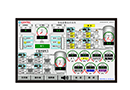
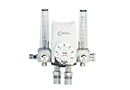
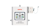
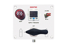
GM3-A Series Dome-bias Fully-Automatic Analog Hybrid Manifold Systems
GM3-A Series dome-bias fully-automatic analog hybrid manifold systems is designed to provide an uninterrupted gas supply without any manual adjustments. This system uses liquid cryogenic tank as primary gas source and automatically switches over to the cylinder bank when the tank is below the lower limit. Even in case of a power failure, the system continues to supply gas without interruption. The system is designed to meet the latest edition of NFPA 99 and EN ISO 7396-1 standards.
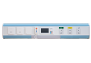
Features
Fully enclosed, tamper- resistant metal cabinet
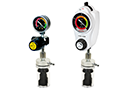
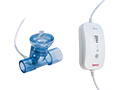
Light indicators provide system status
Dual-stage regulator, stable output pressure and flow
Systems for fuel gas come with an anti-explosive device
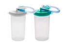
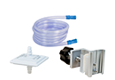
External filter facilitates replacement of filtration elements
Manifold System Layouts
Installation Dimensions
Ordering Information
Gas Service Series Primary Max. Inlet Pressure Secondary Max. Inlet Pressure Delivery Pressure Delivery Flow Outlet Connection Primary Pigtail Specifications Secondary Pigtail Specifications
Oxygen
GM3-AL-O2
GM3-AM-O2
GM3-AH-O2
435 psi (30 bar)
435 psi (30 bar)
435 psi (30 bar)
3000 psi (207 bar)
3000 psi (207 bar)
3000 psi (207 bar)
50~65 psi (3.4~4.5 bar)
100~125 psi (6.9~8.6 bar)
155~185 psi (10.7~12.8 bar)
1060~3500 SCFH (30~100 m3/h)
1060~4200 SCFH (30~120 m3/h)
1060~6000 SCFH (30~170 m3/h)
Rc 3/4"Union
Rc 3/4"Union
Rc 3/4"Union
Rc 3/4"Union
Rc 3/4"Union
Rc 3/4"Union
Pigtail,CGA540
Pigtail,CGA540
Pigtail,CGA540
Air
GM3-AL-AIR
GM3-AM-AIR
GM3-AH-AIR
435 psi (30 bar)
435 psi (30 bar)
435 psi (30 bar)
3000 psi (207 bar)
3000 psi (207 bar)
3000 psi (207 bar)
50~65 psi (3.4~4.5 bar)
100~125 psi (6.9~8.6 bar)
155~185 psi (10.7~12.8 bar)
1060~3500 SCFH (30~100 m3/h)
1060~4200 SCFH (30~120 m3/h)
1060~6000 SCFH (30~170 m3/h)
Rc 3/4"Union
Rc 3/4"Union
Rc 3/4"Union
Rc 3/4"Union
Rc 3/4"Union
Rc 3/4"Union
Pigtail,CGA346
Pigtail,CGA346
Pigtail,CGA346
Carbon Dioxide
GM3-AL-CO2
GM3-AM-CO2
435 psi (30 bar)
435 psi (30 bar)
2175 psi (150 bar)
2175 psi (150 bar)
50~65 psi (3.4~4.5 bar)
100~125 psi (6.9~8.6 bar)
1060~1750 SCFH (30~50 m3/h)
Rc 3/4"Union
Rc 3/4"Union
Rc 3/4"Union
Rc 3/4"Union
Pigtail,CGA320
Pigtail,CGA320
Argon, Nitrogen
GM3-AL-IN
GM3-AM-IN
GM3-AH-IN
435 psi (30 bar)
435 psi (30 bar)
435 psi (30 bar)
3000 psi (207 bar)
3000 psi (207 bar)
3000 psi (207 bar)
50~65 psi (3.4~4.5 bar)
100~125 psi (6.9~8.6 bar)
155~185 psi (10.7~12.8 bar)
1060~3500 SCFH (30~100 m3/h)
1060~4200 SCFH (30~120 m3/h)
1060~6000 SCFH (30~170 m3/h)
Rc 3/4"Union
Rc 3/4"Union
Rc 3/4"Union
Rc 3/4"Union
Rc 3/4"Union
Rc 3/4"Union
Pigtail,CGA580
Pigtail,CGA580
Pigtail,CGA580
GM3-A
Series
L
Delivery Pressure
- O2
Gas Service
- U
Standard Code
- ( 5L x 5R
Number of Cylinders (left-hand / right-hand)
- S
Manifold System Layout
2 )
Cylinder Valve Spacing
GM3-A USA (ISO)
L: 55 psi (5 bar)
M: 100 psi (8 bar)
H: 185 psi (10 bar)
O2: Oxygen
AIR: Air
CO2: Carbon Dioxide
IN: Ar, N2
U: USA Standard
E: ISO Standard
1L x 2R: One cylinder on the left,
Two cylinders on the Right
5L x 5R: Five cylinders on the left,
Five cylinders on the Right
...
Note: Direction of piping (Right or Left) is
indicated by facing the manifold.
S: Standard layout
L: “L" Shape layout
U: “U" shape layout
D: Crossover layout
X: Staggered layout
1: 5"" (127 mm)
2: 10"" (254 mm)
3: 13"" (330 mm)
4: 18"" (457 mm)
Download
2D
3D