Language
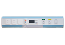
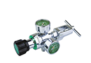
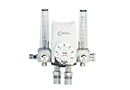
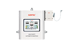
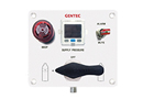
GM1E-A Series Dome-Bias Semi-Automatic Manifold Systems
GM1E-A series Dome-bias Semi-automatic Manifold System is designed to provide an uninterrupted gas supply. It consists of a primary bank and a reserve bank of cylinders. When the pressure in the primary cylinder bank reduces to the preset value, the changeover takes place automatically to provide continuous supply of gas from the reserve bank. The priority handle should be manually switched during cylinder change.
Features
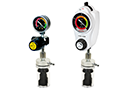
Pressure gauge indicates gas source and outlet pressure
Relief valve at outlet for protecting downstream piping
Pressure switch port is available
Mechanical dome-bias changeover design
Priority Indicator valve
Suitable for high flow system; rated for 120 m3/h (4200 SCFH)* to 170 m3/h (6000 SCFH)**
Installation Dimensions
Manifold System Layouts
Ordering Information
Gas Service Series Max. Inlet Pressure Delivery Pressure Max. Delivery Flow Outlet Connection Pigtail Specifications
Oxygen
GM1E-AL-O2
GM1E-AM-O2
GM1E-AH-O2
3000 psi (207 bar)
3000 psi (207 bar)
3000 psi (207 bar)
100~145 psi (7~1 bar)
170~230 psi (12~16 bar)
200~270 psi (14~18 bar)
3500 SCFH (100 m3/h)
4200 SCFH (120 m3/h)
6000 SCFH (170 m3/h)
3/4" NPT (F)
3/4" NPT (F)
3/4" NPT (F)
Pigtail,CGA540
Pigtail,CGA540
Pigtail,CGA540
Air
GM1E-AL-AIR
GM1E-AM-AIR
GM1E-AH-AIR
3000 psi (207 bar)
3000 psi (207 bar)
3000 psi (207 bar)
100~145 psi (7~1 bar)
170~230 psi (12~16 bar)
200~270 psi (14~18 bar)
3500 SCFH (100 m3/h)
4200 SCFH (120 m3/h)
6000 SCFH (170 m3/h)
3/4" NPT (F)
3/4" NPT (F)
3/4" NPT (F)
Pigtail,CGA346
Pigtail,CGA346
Pigtail,CGA346
Nitrous Oxide
GM1E-AL-N2O
GM1E-AM-N2O
GM1E-AH-N2O
3000 psi (207 bar)
3000 psi (207 bar)
3000 psi (207 bar)
100~145 psi (7~1 bar)
170~230 psi (12~16 bar)
200~270 psi (14~18 bar)
1060 SCFH (30 m3/h)
1060 SCFH (30 m3/h)
1060 SCFH (30 m3/h)
3/4" NPT (F)
3/4" NPT (F)
3/4" NPT (F)
Pigtail,CGA326
Pigtail,CGA326
Pigtail,CGA326
Carbon Dioxide
GM1E-AL-CO2
GM1E-AM-CO2
GM1E-AH-CO2
2175 psi (150 bar)
2175 psi (150 bar)
2175 psi (150 bar)
100~145 psi (7~1 bar)
170~230 psi (12~16 bar)
200~270 psi (14~18 bar)
1060 SCFH (30 m3/h)
1060 SCFH (30 m3/h)
1060 SCFH (30 m3/h)
3/4" NPT (F)
3/4" NPT (F)
3/4" NPT (F)
Pigtail,CGA320
Pigtail,CGA320
Pigtail,CGA320
Argon, Helium, Nitrogen
GM0E-AL-IN
GM1E-AM-IN
GM1E-AH-IN
3000 psi (207 bar)
3000 psi (207 bar)
3000 psi (207 bar)
100~145 psi (7~1 bar)
170~230 psi (12~16 bar)
200~270 psi (14~18 bar)
3500 SCFH (100 m3/h)
4200 SCFH (120 m3/h)
6000 SCFH (170 m3/h)
3/4" NPT (F)
3/4" NPT (F)
3/4" NPT (F)
Pigtail,CGA580
Pigtail,CGA580
Pigtail,CGA580
GM1E-A
Series
L
Delivery Pressure
- O2
Gas Service
- U
Standard Code
- ( 5L x 5R
Number of Cylinders (left-hand / right-hand)
- S
Manifold System Layout
2 )
Cylinder Valve Spacing
GM1E-A USA (ISO)
L: 55 psi (5 bar)
M: 100 psi (8 bar)
H: 185 psi (10 bar)
O2: Oxygen
AIR: Air
N2O: Nitrous
Oxide
CO2: Carbon
Dioxide
IN: Ar, He, N2
U: USA Standard
E: ISO Standard
1L x 2R: One cylinder on the left,
Two cylinders on the Right
5L x 5R: Five cylinders on the left,
Five cylinders on the Right
...
Note: Direction of piping (Right or Left) is
indicated by facing the manifold.
S: Standard layout
L: “L" Shape layout
U: “U" shape layout
D: Crossover layout
X: Staggered layout
1: 5"" (127 mm)
2: 10"" (254 mm)
3: 13"" (330 mm)
4: 18"" (457 mm)
Download
2D
3D